


ENTER YOUR DIMENSIONS
Select Your Spring Type
COMPRESSION
EXTENSION
TORSION
Select Your Unit of Measurement
Warning Messages
Table of Content:
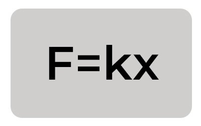
Hooke's Law: Hooke's Law, a fundamental principle developed in the 17th century by Robert Hooke that asserts the force required to compress or extend a spring by a certain distance is proportional to that distance. Mathematically, Hooke's Law is expressed as F=kx, where F represents the spring force applied to the spring, k is the spring constant (indicative of the spring's stiffness), and x is the displacement of the spring from its original length. In the context of compression springs and extension springs, this relationship is crucial for determining the maximum load that the spring can withstand and its behavior under different loading conditions.
Hooke's Law Spring Force Equation states: F= kx
Where:
F = The spring force (in Inches );
K = The spring constant (in Lbs / in ); and
X = The Displacement or Travel (in inches) (compression or extension)
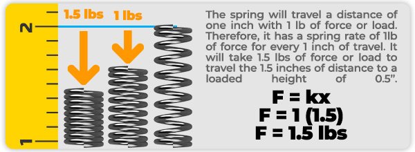
In the dynamic and rapidly evolving field of product design and manufacturing, achieving precision in the application of mechanical forces is paramount. This precision becomes critical when dealing with the functionality and reliability of spring mechanisms, which are ubiquitous in various applications from automotive suspensions to electronic device buttons. At the forefront of this quest for precision is Hooke's Law, a fundamental principle that defines the linear relationship between the force applied to a spring and the spring's displacement or compression.
You compress the spring by 2 inches, your load will be 20lbs
Formula: Rate of 10 lbs x 2 inches of travel = 20 lbs of load or force.
This article embarks on a detailed exploration into the development, utility, and transformative potential of a specialized tool: the Hooke's Law calculator, also known as the spring force calculator. Targeting a broad audience, including makers, manufacturers, inventors, innovators, and industry enthusiasts, we delve into insightful case studies, tackle design challenges, and highlight practical applications of this principle. We place a particular focus on cutting-edge tools such as Spring Creator 5.0 and the Online Spring Force Tester, showcasing their vital roles in bringing the theoretical aspects of Hooke's Law to practical, real-world applications.
Incorporating Hooke's Law formulas into the understanding and application of spring mechanics enhances the depth of analysis for various types of springs, including compression, extension, torsion, and conical springs. Each type of spring operates under the same fundamental principle—that the force exerted by the spring is proportional to its displacement—but the specific formulas and parameters vary based on the spring's design and intended function. Below, we expand upon the discussion by detailing the formulas for these four types of springs, providing a comprehensive guide for makers, manufacturers, inventors, innovators, and industry enthusiasts.
F=kx
F is the force exerted by the spring (in Pounds, Lbs).
k is the spring constant, also known as the rate (in Pounds of force per Inch of compression, Lbf/in).
x is the displacement of the compression spring from its Free Length (in inches, in).
Example: A compression spring has a (k) rate of 6.580 lbs of force per inch of compression or (travel)
You compress the spring by (X) 3 inches, your load will be 20 lbs
Formula: Spring Rate of 6.580 lbs x 3.040 inches of travel = 20 lbs of load or force.
All Specs based on Part Number: PC085-1100-12900-MW-5000-CG-N-IN
Which has the following dimensions in inches:
| k Spring Rate Per Inch: | 6.580 Lbs/in |
| Maximum Safe Travel: | 3.904 inches |
| Load 1: | 20 lbf @ 3.040 inches of Travel / Deflection |
| Max Load: | of 25.683 lbs @ 3.904 inches of safe travel |
| Wire Diameter: | 0.085 inches |
| Outer Diameter: | 1.100 inches |
| Total Coils: | 12.900 |
|
Material Type: |
Music Wire (MW) ASTM A-228 |
|
Free Length: |
5.000 inches |
| End Types: | Closed and Ground (CG) |
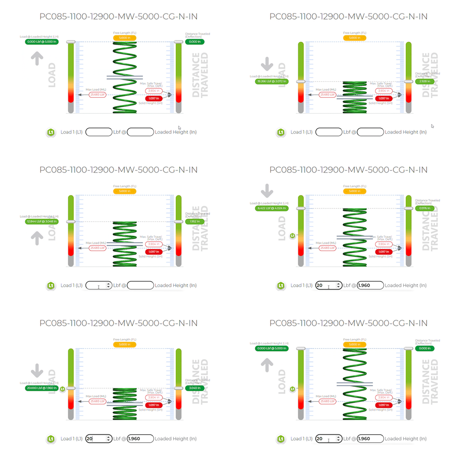
Compression springs are designed to operate with a compressive force, and the spring force increases as the spring is compressed. The spring constant k indicates the stiffness of the spring, with a higher value indicating a stiffer spring.
The development of an intuitive and accurate spring force calculator encapsulates a significant technical challenge, bridging the gap between Hooke's Law's theoretical foundation and its practical application in engineering and design. This tool must cater to a wide range of users, from students and educators seeking to understand the basics of spring mechanics to professional engineers and designers analyzing complex systems. An essential aspect of this development is creating a user-friendly interface that creates thousands of additional spring designs that are weaker and stronger versions of the spring specs just entered. Moreover, the calculator must incorporate sophisticated algorithms that accurately compute the spring force equation, taking into account the nuances of spring behavior under various conditions. The addition of visual aids, like 3D spring CAD views and spring force animations depicting spring compression and extension, further enhances user understanding. These visualizations help demystify the impact of changing different parameters, such as wire diameter or coil pitch, on the spring's force characteristics, making the calculator not only a tool for calculation but also a medium for education and exploration.
Automotive Suspension Design:
The automotive industry presents a complex challenge for engineers seeking to design suspension systems that adapt to changing spring loads and maintain optimal performance under a variety of road conditions. Utilizing a spring force calculator enables these professionals to meticulously calculate spring constants and other critical parameters, ensuring the suspension system provides the necessary balance between stiffness for handling and flexibility for comfort. This precise calculation leads to the development of vehicles that offer enhanced control and stability, improved passenger comfort, and increased safety, demonstrating the practical application of Hooke's Law in optimizing spring performance.
Consumer Electronics:
In the area of consumer electronics, where devices are subject to frequent use, ensuring the durability and responsiveness of button springs is a nuanced challenge. Designers leverage the spring force constant calculator to meticulously determine the ideal spring specifications that will maintain a consistent tactile feedback over thousands of presses. This application of Hooke's Law enables the creation of devices that not only meet the functional requirements of durability and reliability but also enhance the user experience through the quality of tactile interaction, showcasing the law's versatility beyond traditional mechanical applications.


Spring Creator 5.0: This sophisticated spring software tool represents a leap forward in spring design and simulation, offering users a comprehensive platform to calculate and visualize the effects of various design choices on spring behavior. By inputting specific criteria such as material type, wire diameter, outer diameter and number of coils, users can utilize this tool to calculate the optimal spring constant and visualize the spring's performance under different loads. This capability is invaluable for designers looking to optimize spring parameters for specific applications, providing a high level of precision and confidence in the resulting designs.
Online Spring Force Tester: Complementing theoretical calculations, the Online Spring Force Tester offers a practical approach to verifying the accuracy of spring designs. By allowing users to measure the actual force exerted by a spring at various displacements, this tool bridges the gap between theoretical predictions and real-world performance. It enables designers and engineers to validate their spring blueprints against empirical data, ensuring that the final product meets the desired specifications and performs as expected in its application.
The design and optimization of springs are influenced by a myriad of factors, including material selection, environmental conditions, and manufacturing spring indexes. These variables introduce complexities that can significantly impact the performance and reliability of the final product. Advanced tools like Spring Creator 5.0 address these challenges by providing access to comprehensive material databases and incorporating the ability to simulate different environmental conditions and manufacturing variations. This holistic approach enables designers to anticipate potential issues and make informed decisions, selecting appropriate spring rates and materials that align with the specific requirements of their application.

Extension Spring example based on:
Part Number: PE095-750-50368-SST-6000-CO-N-IN
Which has the following dimensions in inches:
|
k Spring Rate Per Inch: |
7.157 Lbs/in |
|
Maximum Safe Travel: |
4.046 inches |
|
Load 1: |
35 lbs @ 3.728 inches of Travel / Deflection |
|
Max Load: |
of 37.279 lbf @ 4.046 inches of safe travel |
|
Wire Diameter: |
0.95 Music Wire |
|
Outer Diameter: |
0.750 |
|
Length Inside Hook: |
6.000 |
|
Total Coils: |
50.368 |
| Hook Type: | Crossover |
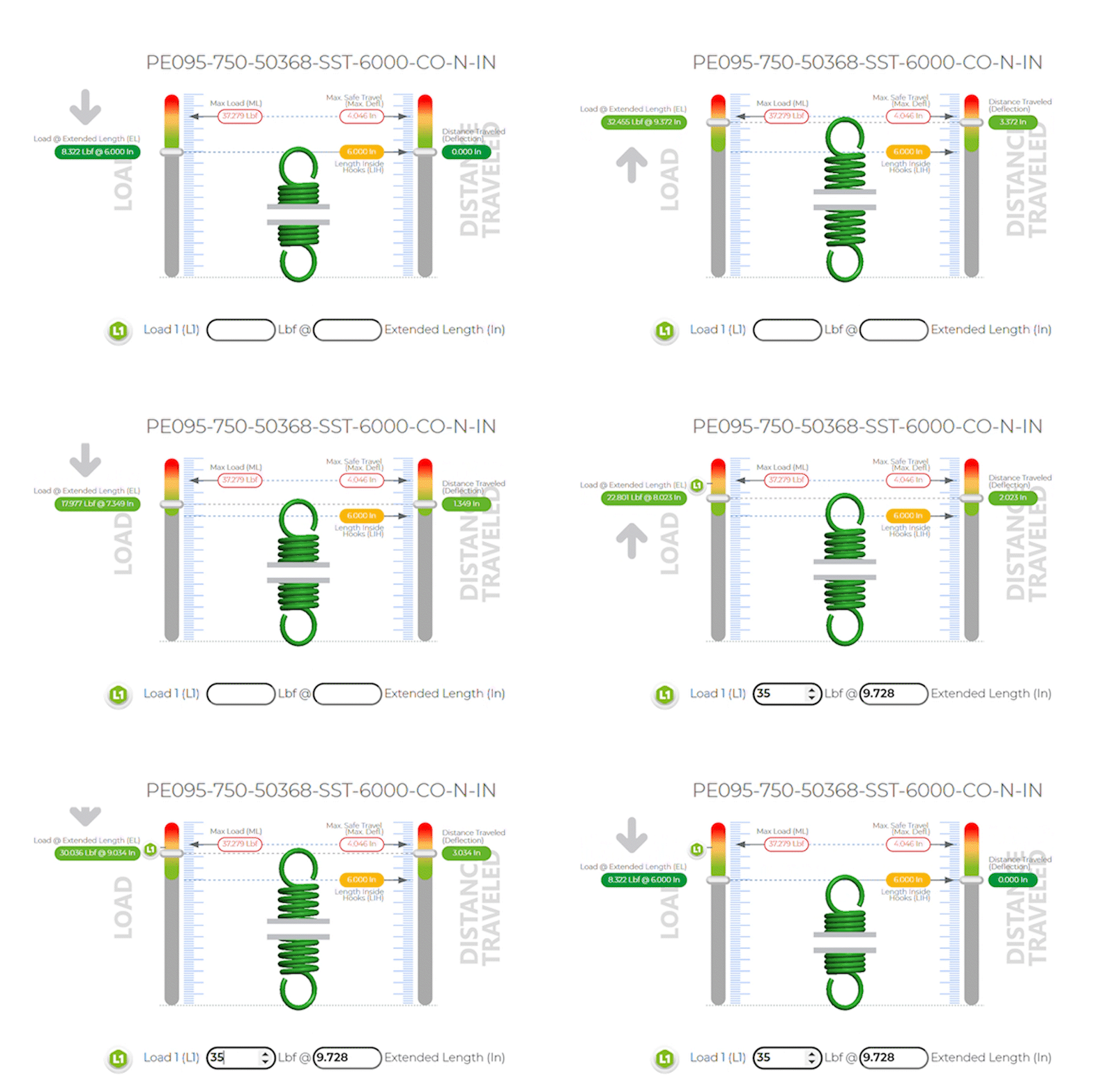
Extension springs are similar to compression springs in their operation, but they are designed to absorb energy and exert a force when stretched. The same basic formula applies, but in this context, x represents the length by which the spring is extended beyond its natural length inside hook or unstretched state.
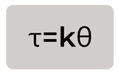
Formula: τ=kθ
τ is the torque exerted by the spring in (Inch-Lbs, in/lbs).
k is the torsional stiffness of the spring in Inch-Lbs / per degree, In·lbs/Deg.
θ is the angle of twist from its free position (in radians).
Example: A torsion spring has a ( k ) rate of 0.020 inch-lbs of force per degree of rotation or (deflection)
You torque or twist the spring by (X) 50 degrees, your torque will be 1.000 inch-lbs of torque
Formula: Rate per degree of 0.020 inch-lbs x 50 degrees of travel = 1.000 inch-lbs of torque @ 50 degrees of travel or deflection.
All Specs based on Part Number: PT045-357-4250-SST-RH-1300-N-IN
Which has the following dimensions in inches:
| k Spring Rate per Degree: | 0.020 inch-lbs/degree |
|
Maximum Safe Travel: |
77 Degrees |
|
Torque 1: |
1.00 in-lbs @ 50 Degrees of Travel / Deflection |
|
Max Load |
of 1.581 in-lbs @ 77 degrees of safe travel |
|
Wire Diameter: |
0.045 302 Stainless Steel |
|
Outer Diameter: |
0.357 |
|
Total Coils: |
4.250 |
| Leg Lengths (Typical): | 1.300 |
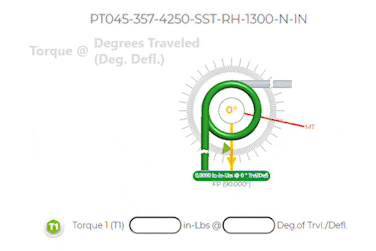
Torsion springs work on the principle of torquing or twisting. They exert a torque or rotational force when they are twisted. The torsional stiffness k determines how much torque is required to twist the spring by a certain degree of travel or deflection.
Formula: F= Gd4/8D3N x
F is the force exerted by the spring.
G is the modulus of rigidity of the material.
d is the wire diameter.
D is the mean diameter of the spring.
N is the number of active coils.
x is the displacement of the spring from its equilibrium position.
Conical springs, or tapered springs, have coils that are not uniform in diameter. The formula for conical springs takes into account the varying diameter of the coils, providing a more complex calculation that reflects the unique geometry of these springs.
By precisely calculating the load of a spring or the spring compression force required in each application, Hooke's Law enables designers to achieve the desired performance characteristics, ensuring functionality and durability in the final product. For example, determining the optimal spring constant is crucial for automotive engineers designing suspension systems that balance vehicle control with passenger comfort, and for consumer electronics designers ensuring the longevity and responsiveness of button mechanisms.
The transition from theoretical equations to tangible, functional designs is a critical step in the application of Hooke's Law. Tools that provide dynamic real time spring movement visualizations and simulations play a pivotal role in this process, transforming abstract concepts into clear, understandable visual representations. For instance, Spring Creator 5.0's ability to visually simulate the effects of altering spring design parameters offers designers a powerful tool for exploring the practical implications of their choices. The Online Spring Force Tester within spring creator 5.0 offers visual aids that not only facilitate a deeper understanding of spring mechanics but also empower designers to experiment and innovate, pushing the boundaries of what is possible in spring design and application.
The Hooke's Law calculator, augmented by state-of-the-art tools like Acxess Spring's Spring Creator 5.0 and the Online Spring Force Tester, stands at the intersection of theory and practice in the field of mechanical spring engineering and design. These tools embody the fusion of the scientific principle of springs and technological innovation, enabling professionals across various industries to design, test, and manufacture springs with an unprecedented level of accuracy and confidence. As we continue to advance in our understanding and application of Hooke's Law, these technologies offer a pathway to new discoveries and innovations, shaping the future of mechanical design and spring manufacturing.
Created by Alfonso Jaramillo J
President Acxess Spring
Over 40 Years of Experience in Spring Engineering and Manufacturing

Your 3D is being generated, 3D generation Will take approximately 15 seconds. Your 3D Will load automatically on this page.

Your 3D is being generated, 3D generation Will take approximately 15 seconds. Your 3D Will load automatically on this page.
Spring Creator is an Acxess Spring Product, You will be redirected to acxesspring.com for your purchase
Click to open acxesspring.com
